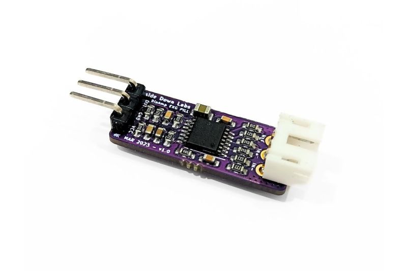
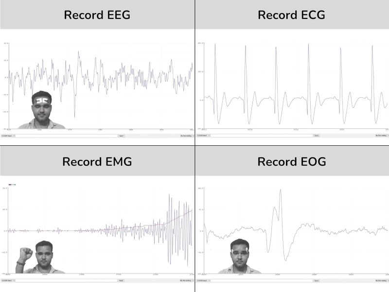
The BioAmp EXG Pill is an advanced, high-performance bio-potential signal amplifier designed to record publication-grade biopotential signals. It can be used to measure Electrocardiogram (ECG) from the heart, Electromyogram (EMG) from muscles, Electrooculogram (EOG) from eye movements, or Electroencephalogram (EEG) from the brain. The "unassembled" version provides the PCB and all necessary components, allowing users to solder the parts themselves, which is a great educational experience for understanding the circuit's design and function.
✨ Key Features and Benefits
- Versatile Use: Can be configured to measure ECG, EMG, EOG, or EEG signals.
- High-Quality Signal: Designed to produce low-noise, high-fidelity signals suitable for scientific publication.
- Open-Source Hardware: The design is open-source, promoting transparency and community development.
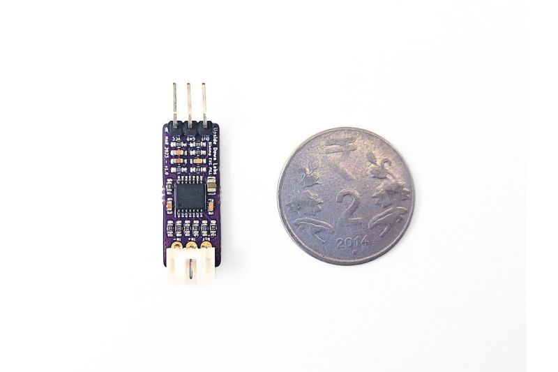
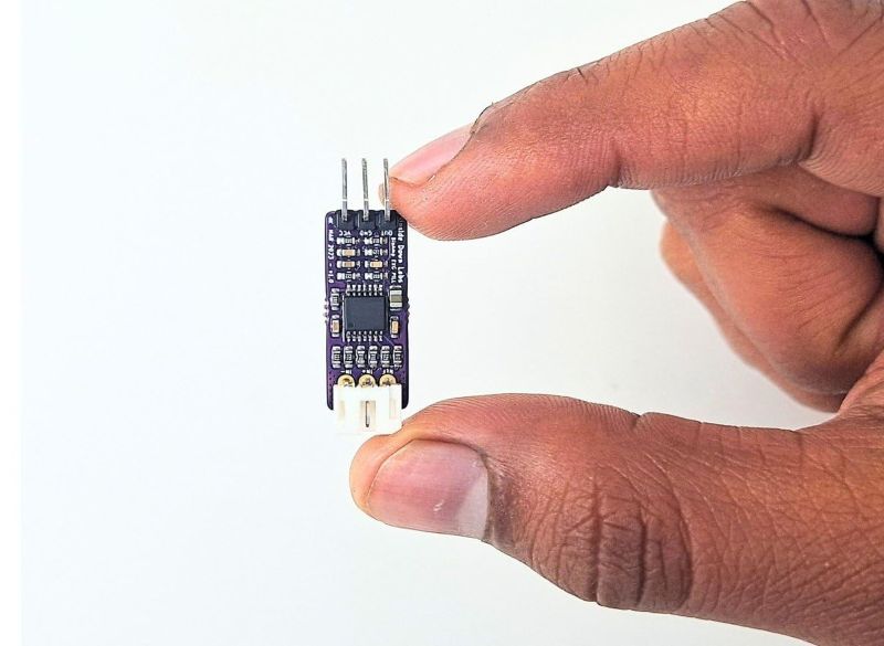
- Compact Form Factor: Small size makes it ideal for wearable and portable projects.
- Unassembled Kit: Offers a hands-on learning experience in soldering and electronics.
- Easy Integration: Can be interfaced with any microcontroller with an analog-to-digital converter (ADC).
- Built-in Filters: Includes filters to remove ambient noise and power line interference.
🔧 Material and Construction Details
| Component | Material | Description |
|---|---|---|
| PCB | FR-4 | The main circuit board provided in the kit |
| Amplifier IC | Specialized Bio-potential Amplifier | A high-gain, low-noise integrated circuit |
| Passive Components | Resistors, Capacitors, Inductors | Used for filtering and amplification circuitry |
| Connectors | Header Pins / Solder pads | For power, signal, and electrode connections |
| Electrodes | Medical-grade Ag/AgCl | Self-adhesive pads for connecting to the body |
📚 Use Cases and Applications
- Biomedical engineering projects
- Neuroscience and cognitive science research
- Bio-feedback and mind-controlled devices
- Robotics and BCI (Brain-Computer Interface) development
- Wearable health and fitness trackers
- Educational tools for learning about biopotential signals
- Research in human-computer interaction
🔍 Technical Specifications
| Specification | Details |
|---|---|
| Operating Voltage | 3.3V - 5V DC (can vary based on configuration) |
| Output Signal | Analog (0V to VCC) |
| Input Impedance | Very high, to avoid loading the body's signal |
| CMRR | High Common-Mode Rejection Ratio for noise immunity |
| Dimensions | Small, "pill-sized" form factor |
| Output Type | Single-ended output |
🔌 Connection Diagram (General)
| Module Pin | Function | Arduino/MCU Connection |
|---|---|---|
| VCC | Power Input (+) | 3.3V or 5V |
| GND | Ground (-) | GND |
| OUT | Analog Output | Analog pin (e.g., A0) |
| RA / E1 | Electrode 1 | Connects to a specific electrode pad |
| LA / E2 | Electrode 2 | Connects to a specific electrode pad |
| RL / E-Ref | Reference Electrode | Connects to the reference electrode pad |
🧼 Assembly & Maintenance
As an unassembled kit, the main task is proper soldering of all the provided components onto the PCB. A well-soldered board ensures reliable performance. After assembly, proper electrode placement is critical for clean signal acquisition. Electrodes should be placed on clean, dry skin. The module itself is maintenance-free, but electrodes should be replaced regularly as they are disposable.
⚠ Safety Information
This product is intended for research, educational, and hobbyist use only. It is not a medical device and should not be used for diagnosis or treatment. Do not connect this device to patients on life support or other medical support systems. Always follow proper electrostatic discharge (ESD) precautions during assembly. Ensure the power source is within the specified voltage range. The electrodes should only be used on intact, healthy skin.
👍👎 Pros & Cons
| Pros | Cons |
|---|---|
| High-quality, publication-grade signal amplification | Requires soldering skills for assembly |
| Extremely versatile for different biopotential signals | Not a professional medical device, for research and hobby use only |
| Open-source design with community support | Requires good electrode placement and clean signal processing |
| Great for learning electronics and bio-signals | More expensive than basic heart rate sensor modules |
🅿 Product Images: