A Micro SD card breakout board is an essential module for adding mass storage to a microcontroller project. This specific board is designed for 3V logic and power, making it perfectly compatible with microcontrollers like the ESP32, ESP8266, and many others. It provides a simple way to interface a Micro SD card using either the common SPI (Serial Peripheral Interface) or the faster SDIO (Secure Digital Input/Output) protocol, allowing you to easily read and write data for data logging, storing sensor readings, or loading configuration files.
✨ Key Features and Benefits
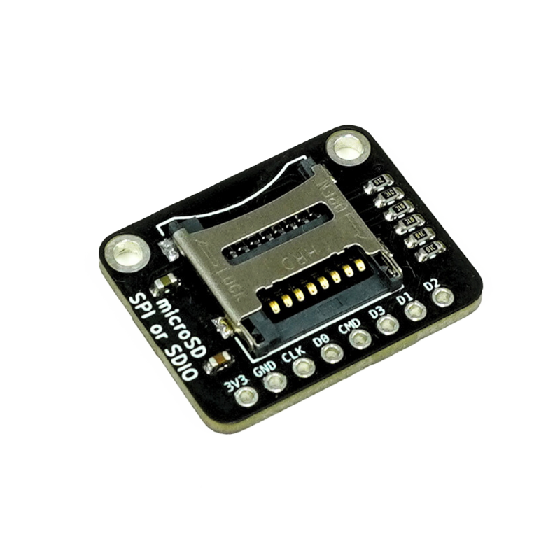
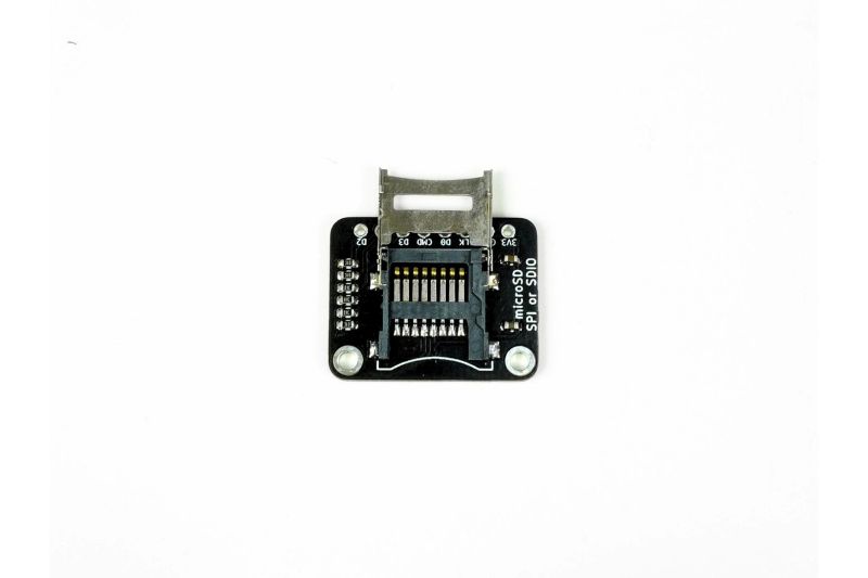
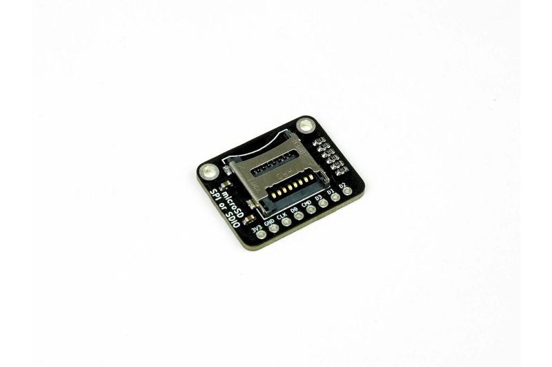
- Provides a socket for a Micro SD card
- Supports both SPI and SDIO communication protocols
- Specifically designed for 3V operation, no level shifters needed for 3.3V MCUs
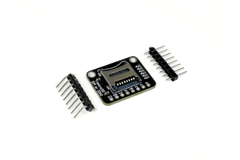
- Compact and easy to integrate into projects
- Allows for reliable data logging and file storage
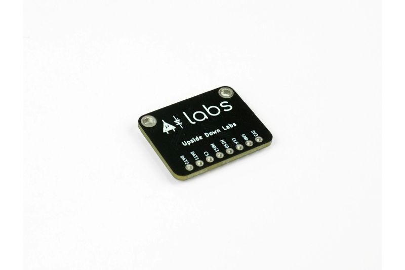
- Comes with labeled pins for easy wiring
- On-board voltage regulator ensures stable power to the card (if applicable)
🔧 Material and Construction Details
| Component | Material | Description |
|---|---|---|
| PCB | FR-4 | The main circuit board of the module |
| SD Card Socket | Plastic and Metal | The mechanical slot for inserting the Micro SD card |
| Resistors & Capacitors | Standard components | Signal conditioning and power filtering |
| Connectors | Standard Header Pins | For VCC, GND, and data lines |
📚 Use Cases and Applications
- Data logging for sensors (temperature, humidity, etc.)
- IoT devices that need to store configuration files
- Digital cameras and audio recorders
- Embedded systems that require a filesystem
- Robotics and autonomous vehicles for logging sensor data
- Educational projects to teach about file systems and memory cards
- Firmware updates and bootloaders for microcontrollers
🔍 Technical Specifications
| Specification | Details |
|---|---|
| Operating Voltage | 3.3V DC |
| Logic Level | 3.3V |
| Communication Protocol | SPI or SDIO |
| Dimensions | Compact, typically around 25mm x 20mm |
| Card Compatibility | Micro SD, Micro SDHC, Micro SDXC |
🔌 Connection Diagram (SPI Mode)
| Module Pin | Function | Arduino/MCU Connection |
|---|---|---|
| VCC | Power Input | 3.3V |
| GND | Ground | GND |
| CS | Chip Select | Digital Pin (e.g., D10 on Uno) |
| SCK | Clock | Digital Pin (e.g., D13 on Uno) |
| MOSI | Master Out, Slave In | Digital Pin (e.g., D11 on Uno) |
| MISO | Master In, Slave Out | Digital Pin (e.g., D12 on Uno) |
🧼 Calibration & Maintenance
This module does not require any calibration. For reliable operation, ensure the Micro SD card is formatted correctly (usually FAT32) before use. Keep the contacts of the card and the socket clean. Avoid inserting or removing the card while the module is powered on to prevent data corruption. The on-board components are designed to be maintenance-free.
⚠ Safety Information
This board is designed for 3.3V operation. Connecting it to a 5V power source or logic level will likely damage the Micro SD card and the board itself. Double-check your microcontroller's logic level and ensure you're using the correct voltage. Do not force the SD card into the slot. Handle the board with care to avoid static discharge, which can harm the sensitive components.
👍👎 Pros & Cons
| Pros | Cons |
|---|---|
| Dedicated 3V design simplifies wiring for 3.3V MCUs | Not directly compatible with 5V Arduino boards without a level shifter |
| Supports both SPI and faster SDIO protocols | Some cheap versions might have poor solder joints |
| Essential for data logging and file storage projects | The physical card can be difficult to insert/remove |
| Low cost and widely available | Requires a filesystem library in code (e.g., SD.h) |
🅿 Product Images: